The electric stove consists of a work table with 4 burners. Most often, each is done at a certain power, which differs from the neighboring burners. The burners have different diameters, very often a heating element serves as a burner - a heating element. A grid can be put on the desktop, it is for ease of use. The power of each cooking zone mainly depends on the specific type.

Cast iron burners are made from alloys of different metals (iron, copper, aluminum), they are usually more powerful (900-1600 W), burners in the form of a spiral (TEN) are usually made with a power of 400-600 W.

There are 2 heaters installed in the electric stove oven, often in the form of rectangular heating elements. The power of one such heating element in the regions is 1000-1700 watts. The heating elements of the oven are located in an upright position. The oven also has a light to monitor the cooking process. On the control panel of the electric stove, you can see the control knobs that are designed to control the burner and oven. Next to each handle there may be a built-in indicator that notifies of the inclusion of a particular burner. Electric stove diagram:

In older models of electric stoves, the knob simply switches the operating modes of the burner, in modern gas stoves, where digital control is implemented, there is a system of smooth temperature control, and in the latest innovations, the knobs are completely replaced by sensors. The current consumed by an electric stove can be up to 20 amperes at full power, and to withstand this current, good, powerful contacts of the socket and mains plug are necessary. After installing the electric stove and connecting it to the outlet, it is necessary to check the phase between "ground" and zero phase, the ohmmeter reading should be infinity and 4-10 ohms, respectively. After that, you can apply voltage to the electric stove.
This article will consider the connection diagrams for electric stoves, as well as a practical guide on how to install such a stove on your own. In addition, you can use help and order this service inexpensively. But if you are used to doing everything yourself, this article is for you. After reading the article to the end in detail, you can cope with this task without any problems.
All household appliances consume electricity, and naturally, when it comes to an electric stove, it is clear that the connection of such devices requires mandatory grounding. Currently, the market uses sockets and plugs of the RSh-VSh standard. These connectors have a grounding contact. These sockets are available for both 220 V and 380 V. They were designed back in the days of the Soviet Union, and are used to this day, however, time has made its own adjustments, modifying them for hidden wiring.
Brief content of the article.
Preparing to connect the electric stove.
Take your time, before starting work on connecting your electric stove, you must familiarize yourself with the instructions attached to it, namely, see the power consumption and connection schemes. And also make sure that all safety requirements and connection rules are followed. This requires:
Check the power cable. It must go directly from the electrical panel and have three conductors for connecting to 220V or five conductors for connecting to 380V. A grounding conductor must be mandatory, in any case.
Check circuit breaker. For an electric stove, a separate 25-40A circuit breaker must be installed in the switchboard, depending on the number of phases in the cable that is connected to the stove. If at 220V, this is usually 32A. If at 380V it is usually a 25A automatic machine.
Check cable cross-section. This item is a must for those who have an old house with old aluminum wiring, respectively. The fact is that in some old houses the electrical wiring is not designed for the power of modern stoves.
Table 1. To check the correspondence of the cross-section of the supply cable to the power consumption of the electric stove.
|
Cable section |
Copper conductors |
Aluminum conductors |
||||
|
Current, A |
Electric stove power, kW. |
Current, A |
Electric stove power, kW |
|||
|
220V |
380V |
220V |
380V |
|||
|
12,0 |
||||||
Check and label wires. Modern wiring makes this task very easy, because the wires of the new sample differ in color, most often the ground wire is insulated in green or yellow-green colors, zero is blue, phase is white, red, brown. Old-style wiring presents a difficult task, because all the wires in it are the same color, which means that in order to determine which wire is the ground, you will need to turn off the power supply in the apartment.
Next, using an ohmmeter, you need to check the wires, for this one probe must be fixed so that it touches the battery and the water pipe, while the second one checks the wires. The resistance to ground will be only a couple of tens of ohms, while the rest of the wires will show much more resistance. In order to somehow distinguish between the wires, you should mark them with multi-colored markers or simple electrical tape, if you have one at hand. If you already had an electric stove or a socket for it, check is not required, since everything is already connected there to you, to its terminals. Without checking the wires and 100% detection of zero, ground and phase, connection is prohibited.
Sockets and cable for connecting an electric stove.
Depending on the chosen connection scheme 220V or 380V, we may need the following materials. Directly the socket itself, and a piece of cable. From the tool, a set of screwdrivers, a knife, a multimeter and an indicator screwdriver.
Choosing a socket for connecting an electric stove. The design of the finished pair completely and completely eliminates the possibility of errors in connecting the electric stove. At the moment, RSh-VSh sockets are manufactured in Ukraine, and this has a bad effect on their quality. After all, they are designed to work with a power of 7 kW, while most electric stoves produced today are designed to work with capacities of 8-10 kW. Here we will be helped out by replacing the plug-socket pair, especially since in our time there are wonderful sets of Belarusian production on the market. They are made in a modern design and fit both domestic and European stoves, which most often do not have cords and plugs in the connection set.
Figure 1. Sockets for connecting an electric stove.
Belarusian connectors. The main advantage of the Belarusian connectors is the combination of their price and quality. Undoubtedly, they are more expensive than Ukrainian ones, but much cheaper than European counterparts. In their work, they can withstand high power, and are designed to work more than 32A, in addition, they are available on the market in versions for both open and closed wiring.
Connection via box, no plug.

Figure 2. Terminal box for connecting an electric stove.
In modern houses, new buildings, special terminal boxes are increasingly used to connect electric stoves. This connection option is universal and, unlike sockets, is suitable for connecting both 220V and 380V.
In photo # 2, a three-core cable comes out of the wall and connects to the corresponding contacts of the box (the contacts on the box are signed). From the box, a flexible (black) cable comes out to the electric stove.
Selection of the brand and section of the cable.

Figure 3. Cable for connecting the electric stove.
Choice of cable. To connect the electric stove, we also need a three-core or five-core copper flexible wire 1.5-2 meters long. I always take a PVS-3x4 or PVS-5x4 cable. The first digit means the number of cores, the second digit is the cross-section of the wire.
Electric stove connection diagrams.
As a rule, removing the terminal block cover from the rear panel, you will find not only a row of copper jumpers, but also a diagram of three connection options located next to it. They are designed for three-phase, two-phase and single-phase connection to the mains. Next, we will consider in detail all existing connection schemes.

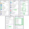
Figure 4. Sticker with options for connecting the electric stove. It is usually located on the back cover.
Connection diagram for an electric stove for 220 V.
The most common option is considered to be connected to a single-phase network. To do this, you need to set all the jumpers in accordance with the figure. Namely, we put two jumpers included in the kit between terminals 1,2,3 and connect the phase wire L1 to them. Next, put a jumper between terminals 4,5 and connect the neutral wire N to them. There remains one terminal with the grounding symbol, we connect the PE ground wire to it. It is advisable to observe the color coding, that is, connect the blue wire to zero, yellow, green or yellow-green to the ground, the rest of the colors to the phase contact.

Figure 5.
Note that on different plate models, the location of the grounding pin can be on either the right or left side. Therefore, when connecting the ground wire, be sure to check for the ground symbol next to the terminal.

Figure 6.
Wiring diagram for a 380V electric stove.
There are two connection options, three-phase and two-phase. It is preferable to choose the option with three phases for even distribution of the load. For a three-phase connection, you will need a 5-pin socket, and for a two-phase connection, you can purchase a 4-pin socket.
Three-phase connection.

Figure 7. Wiring diagram of a 380 V electric stove to a three-phase network.
Let's first consider the option of a three-phase connection. Again we look at the diagram and, in accordance with it, we install only one jumper between terminals 4,5 and connect the neutral wire N to them. Next, we connect the phase wires L1, L2, L3 to terminal 1,2,3. Connect the PE wire to the terminal with the ground symbol.
Two-phase connection.

Figure 8. Wiring diagram for a 380 V two-phase electric stove.
In accordance with the diagram, we connect the phase conductor L1 to terminal 1, install a jumper between terminals 2,3 and connect the phase conductor L2 to them. Install a jumper between terminals 4,5 and connect the neutral N wire to them. Connect the PE ground wire to the terminal with the ground symbol.
Attentive readers have probably noticed in the picture that there is another option for three-phase connection (on some models) without using zero. This option was created for America, in any case, do not use it in Russia. The fact is that in this circuit, the supply voltage must be 110V.

Figure 9. Three-phase connection diagram without using zero.
The final stage, verification.
Before connecting the electric stove to the socket, turn on the machine and check the correctness of the connection at the socket. Make sure with an indicator screwdriver that the phase wire is on the phase terminal. Check again that the wires on the plug are connected correctly. The resistance between the grounding pin on the plug and the body of the cooker must be zero. After that, you can connect the plug and slowly set all operating modes on the plate in order to make sure that the wiring will withstand the load. That is, the machine does not turn off, and the cable does not heat up. So everything is buzzing! You did it!
The kitchen stove, as practice shows, is to a greater extent a stationary device, and having installed it once, you will not change its place every day or even once a week, and therefore there are schemes for connecting the electric stove directly, without a plug and socket. As a rule, in this case, the electric stove is connected through a junction box with a carbolite or ceramic terminal block.
Video instruction for self-connecting the electric stove.
Electricity is a serious and dangerous business, but many jobs do not require high qualifications and can be done independently without the involvement of specialists. For example, you can connect an electric stove with only a distant idea of electricity. Especially if the socket is already installed. All that remains is to install the plug on the cord and connect it correctly to the plate connectors. The situation is worse if it is necessary to pull the line from the shield, but even here you can cope without help. Just remember that all work is performed with the power supply disconnected.
Scheme and connection methods
Electric household stoves are powerful equipment, their current consumption is about 40-50 A. This means that it is necessary to connect the electric stove to a dedicated power line. It must be powered directly from the apartment or house panel. Power is supplied through an RCD and a circuit breaker. The stove itself can be connected via a socket and a plug (special power), a terminal box. Also, the line from the machine can be directly connected to the input terminals on the rear wall.
More reliable connection - directly to the input terminals of the plate. In this case, there is a minimum number of points of contact, which increases reliability. But this method is not entirely convenient: you can only turn off the power supply automatically. The problem is approximately the same when using a terminal box, with the only difference that there are more connection points.
The most commonly used connection is a socket and a plug. It is more convenient and familiar. Since the equipment is powerful, they use not ordinary household devices, but special ones, which are also called power ones - for their ability to withstand significant current loads.
Please note that when connecting powerful electrical equipment, grounding is required. Without it, you will be denied warranty repairs, and its absence is life-threatening, so it's better not to risk it.
Electrical parameters and ratings of circuit breakers
How to connect an electric stove to a 220 V network
All the above schemes were specifically for a single-phase 220 V. To connect, you need a three-core cable, a three-pin power socket and a plug with a rated current of at least 32 A. We must say right away that the connection of equipment of different brands is fundamentally no different. It doesn't matter which stove you purchased - Electrolux, Gorenje, Bosh, Beko. Does not matter. All the difference is the different design of the covers that cover the terminal box on the case and different ways of fixing it. Everything else is the same.
First, the cable selected for connection must be connected to the electric stove. On the rear panel, usually at the bottom left, there is a terminal block to which the conductors are brought out.

Nearby are the connection diagrams for different networks.

With a 220 V network, the circuit is on the far right. On the plate, contacts 1,2,3 must be connected with one jumper - this will be the phase (red or brown conductors), the second - contacts 4 and 5 - this is neutral or zero (blue or blue), the sixth contact is ground (green or yellow -green). Electric plates usually come from the store with jumpers already installed, but it does not bother to check.

It is more correct and more reliable to compress the conductors with contact plates, and then connect them. Such a connection is more reliable, but often the conductors are simply twisted around the clamping screw and then tightened. In any case, it is better to observe the color coding - this way there is less chance of making a mistake.

Installing the plug
Next, a plug is connected to the cable. The power plug is collapsible. Unscrew the two fastening screws, remove the cover with contacts. The fixing strip that holds the cable is also removed. Protective insulation is removed from the edge of the flexible cable (by about 5-6 cm), the conductors are straightened, their ends are also stripped of insulation by about 1.5-2 cm. The cut end of the cable is inserted into the plug body.

The clamping screws on the contacts are loosened, the conductors, if they are stranded, are twisted into a bundle. These filaments are twisted around the contacts, tightened with clamping screws.
The distribution of conductors is important and must be connected carefully. The top pin of the plug is usually labeled - the "earth" wire (green) is connected here. When connecting the socket, you must apply the "ground" to a similar connector.

The other two contacts are "phase" and "zero". It is not important where to supply which of them, but when the socket is connected, the "phase" should fall on the "phase", "zero" - on "zero". Otherwise, there will be a short circuit. So before turning on, be sure to check again if the wires are screwed on correctly (phase and zero).
How to determine the phase in an installed outlet
If you already had an electric stove before, and there is an outlet, you need to find in it where the ground, phase and zero are located and, accordingly, connect the wires in the plug. The easiest way to determine is to use a voltage indicator in the form of a screwdriver. It works simply - install the indicator in the place of the expected phase, and look at the LED built into the case. If it is on, then there is voltage and this is a phase. If there is no voltage, the LED does not light up, and this is zero.
The earth is even easier to define: it is contact above or below.
Connection to a three-phase 380 V network
In this case, an automatic machine and an RCD for a three-phase network are bought, the wires must be five-core (the cross-section is determined according to the same table, only the value must be looked at in the 380 V column). The plug and socket must also have five pins.
The connection process itself will not differ in anything, only the number of wires. The difference will be when you connect the wire to the output terminals of the electric stove. Only one jumper will be installed - on pins 5 and 6. All the rest are connected with separate conductors.

It is also necessary to track the position of "ground" and "neutral" (or they say "zero"). The color matching of the conductors on the phases is not critical, but it is more convenient if they also coincide.
Probably everyone knows that connecting a gas stove should be entrusted to professional craftsmen. But with an electric stove, the question is somewhat different. Many people think that it is enough just to plug it in and you can “wash your hands”. In fact, this is not the case. The electric stove is a very powerful electrical appliance, therefore, when connecting it on its own, it is simply necessary to strictly observe a number of requirements. We will talk about them in this article.
General requirements for connecting electric stoves
Despite the abundance of various models and brands of electric stoves (hansa, combustion, etc.), the general requirements for their connection are almost the same. A slight difference exists only in the connection of 220 and 380 volt stoves.
Regardless of the brand, the connection diagram for all plates is the same
So, here are the basic requirements for connecting an electric stove:
- a separate wiring line must be laid for it, equipped with a safety switch;
- the stove should be connected to the power supply either directly or through a terminal block or a special socket;
- the connection must take into account such parameters as "phase", "zero" and "earth".
Let's consider each of the above points in more detail.
Separate wiring line
Most of the apartments, especially new buildings, are equipped with a separate power line for the electric stove. But if such a line is not provided in your house, then it is necessary to lay it before connecting.
For the power line of the electric stove, a copper three-core wire with a cross section of at least 6 millimeters is suitable.
It is better to use a multicore cable to connect the plate.
A safety switch must be installed on the line, with a capacity of 25 to 40 A.
The power of the machine is selected in accordance with the power of the plate
More precisely, the required power of the machine can be found in the instructions attached to the stove.
The line should be equipped with a differential circuit breaker or an emergency shutdown unit.
Connecting the cable to the stove
Some models are not supplied with a power cable, so you have to plug it in yourself.
To do this, the protective cover on the back of the plate must be removed. It is usually bolted on.
Before starting work, the cover must be removed
The connection of the electric stove can be single-phase (220 volts), two-phase or three-phase (380 volts). In this case, it is very important to know which of the wires is connected to the phase. To do this, you must first use an electrical tester.
Before connecting the stove, the network must be ‘ring’
The terminals of the terminal box of the electric stove are marked with the following markings:
- L1, L2, L3 - phase terminals. As a rule, these are terminals 1,2 and 3;
- N - zero terminals. These are terminals 4 and 5;
- And a ground terminal marked with a special icon.
Most of the boards have jumper wires installed between the terminals. If there are no such jumpers, then with a single-phase and two-phase connection, you will have to make them yourself. For this, you can use small pieces of cable. For these purposes, use a three-core cable (with a single-phase connection) or a five-core (with two- and three-phase).
Single phase
Install jumpers between terminals 1, 2 and 3. Connect the phase wire to terminal 3. Jumpers are placed between terminals 4 and 5. The neutral wire is connected to terminal 5. And the remaining wire goes to the ground terminal.
Single-phase connection with manufacturer jumpers
A more detailed diagram of a single-phase connection is shown in the following figure.
Jumpers are installed between all terminals
Biphasic
Jumpers are installed between terminals 1 and 2. And the wires of the corresponding phases are connected to 2 and 3. Neutral wires are connected to terminals 4 and 5. To the ground terminal - earth wire.
For a two-phase connection, two jumpers are used.
Three-phase
In this case, no jumpers are placed between the terminals. The ground wire is brought out separately.
The wires are attached to the terminals without jumpers
All wire connections are made using special clamps.
Connecting the stove to the mains
The best way is to connect the hob directly to the circuit breaker. This makes it possible to avoid unnecessary connections that can overheat, which lowers the level of security.
The absence of unnecessary connections is considered the safest
But if you want to be able to disconnect the stove from the general power supply, you can install it using a terminal strip or a special socket.
The terminal strip is mounted on the wall, after which the wires of the power supply line are connected to it on one side, and the power cable of the electric stove on the other.
Make sure the terminal block matches the capacity of the hob
IMPORTANT! When connecting to the terminal block, make sure that the wires of the corresponding color are connected to the same terminals as on the plate itself.
Plug-in connection
To connect the electric stove, you must install a special power outlet with grounding.

The purchase of an electric stove for the kitchen in the apartment will present the owner with the problem of connecting the device to the network. The instruction recommends inviting a specialist for these purposes. But this is not always necessary. The network connection diagram is understandable and can be implemented independently. It is equally applicable to a conventional electric stove, with its help you can connect:
- hob,
- induction hob,
- glass-ceramic.
To properly connect a new acquisition with your own hands, you need to spend time and familiarize yourself with the algorithm of actions. It is simple and includes several stages:
- Choice of installation site.
- General requirements.
- Installation of an RCD and an automatic machine.
- Cable installation.
- Selecting the type of connection.
- Connection diagrams.
Before connecting the stove or hob, you should correctly determine the place of its future placement in the apartment relative to the connection point, proximity to the refrigerator and other household appliances:
- The platform on which it is planned to install the stationary model should be as flat as possible in order to ensure a stable horizontal position when adjusting the legs.
- The length of the wire and the distance from the point of connection to the device must allow the device to be freely moved without disconnecting.
- The ten of a conventional electric stove can heat up to 100 ° C, therefore it is not recommended to place the electric stove or hob next to the refrigerator.
- Hot shades can melt plastic furnishings.
- It is also undesirable to place an induction hob or a similar hob next to a refrigerator or other household appliances, the electromagnetic field generated by it negatively affects their operation.
General requirements
It is impossible to correctly connect an electric stove or hob with your own hands without observing certain equipment requirements. In an apartment, this can be done much easier and faster.
Usually, in an apartment of a standard high-rise building, the connection of such devices to the network is carried out with a separate wire already mounted, through a specially provided outlet. This saves time and allows you to quickly connect your hob or hob.
The owners of a private house will have to perform all the work related to the wire, and the installation of other equipment will have to be done independently or with the invitation of a specialist. In this case, you should use:
- a three-core cable with a copper cross-section from 4 to 6 mm, depending on its length;
- a separate automatic machine for an electric stove for installation in a panel for 32 or 40A in accordance with the wire section;
- residual current device;
- an accessible method of grounding.
Residual current device and circuit breaker
An RCD and an auto-breaker are a mandatory element of the kit, which is used to independently connect any household appliance to the network. Their presence will save the device from voltage surges in the network and premature failure:
- They are placed side by side on a mounting rail up to the meter.
- The rated value of the RCD must be greater than the machine.
- The RCD is connected to the counter with the upper phase and zero fasteners, respectively.
- The lower terminals are used for connection to the machine and are brought to zero.
- If a single-pole machine is used, the zero terminal of the RCD is connected to the zero bus.
- With two-pole, it is connected by a zero terminal with the corresponding contact of the machine.
- The phase and zero conductors of a three-core wire are placed on the lower mounts of the machine.
- If the machine is a single-pole neutral wire goes to the corresponding bus.
- Yellow-green or green is for grounding.

Cable installation
To connect the outlet or terminal block with a cable to the electrical panel, you will need to grind the wall yourself. You will have to spend time on the styling hidden in the wall, but it will not spoil the interior. An alternative and less troublesome option, more often used for a house with wooden walls, involves the use of an external box. Slitting and laying in a box are carried out along the shortest route.
Electric stove connection type
Before starting the installation, you need to determine which type of connection is best to use. You can install an electric stove or hob in an apartment or in the kitchen of a private house with three types of network connection:
- direct connection;
- through the terminal box;
- through the outlet.
Direct inclusion
This option can be used if there is no need to disconnect the stove or hob from the mains. It is considered the safest. The absence of additional connections reduces the risk of overheating. If a separate disconnection is required, then a terminal box or socket must be installed.

How to install the terminal box
It is recommended to connect a modern stove to the network without plugging it into an outlet through a high-quality terminal block. You can use a socket in a back box, which is mounted on the outside on the wall, or a metal box for concealed installation. The box is placed at a distance of two meters from the electric stove, at a height of at least 0.6 meters from the floor.

Plug-in
A common option for connecting to the network is to plug it in through an outlet with the obligatory use of grounding.

For these purposes, 3 types of socket can be used in an apartment or in the kitchen of a private house.
Domestic production with the upper grounding arrangement, rotated 90 °.

Belarusian production, which is distinguished by a turn of contacts by 120 ° relative to each other.

European type, where the grounding pin is at the bottom and has a flat section.

If there is no need to install the wiring with your own hands, the corresponding equipment is already available in the apartment or in the kitchen of a private house, the outlet must be checked for phase. This is done with an electric tester.
Schemes
Regardless of the method of connection via a socket or terminal block, the stove or hob can be connected to the network in three ways:
- single-phase;
- two-phase;
- three-phase.
For 220V devices, a single-phase circuit is used, for 380V two or three-phase options. Before connecting the electric stove or hob, you will have to turn it back and remove the protective cover from the terminal box. Possible connection diagrams are usually indicated on the back of the device.

One phase
This is the most common option in a high-rise apartment. It can be used when docking is done with a three-core wire. It is easy to do with your own hands. To properly connect the device, you must use jumpers. They are usually supplied and bolted in the terminal box. If they are not available, copper jumpers with a cross section of 6 mm can be purchased. Five of the six screws are connected by two busbars:
- one bus connects the screws marked with the letter "L" numbered 1, 2, 3;
- the second is used to connect numbers 4 and 5, designated by the letter "N";
- the latter remains free and will be used for grounding.
When connected, the wires are distributed as follows:
- phase (black or brown) at L1,2 or 3;
- zero (blue) for N4 or 5;
- for grounding, the sixth terminal is used with the designation PE.

Two phases
This scheme is more often used for a private house, but it can also be used in an apartment. Docking is done with a four-core wire. In this case:
- one jumper is placed on L1 and L2;
- the other at N4 and N5;
- L3 and the ground screw remain free.
To connect a circuit like this:
- the yellow core is placed on phase A, consisting of terminals L1 and L2, connected by a jumper;
- the core in the red winding goes to the adjacent L3 terminal;
- put in blue on zero N4 and N5, joined by a jumper;
- yellow-green is for grounding.

Three phases
This option is intended for a private house; such a scheme is rarely used in an apartment. Despite the external complexity, it is just as easy to implement it yourself. It is carried out with a cable of four or five cores. Here, only one bus is used to connect the adjacent zero terminals N1 and N2. The cores must be connected in the following order:
- to phase A, contact L1 goes yellow;
- for phase B, contact L2 - green;
- for phase C, contact L3 - red;
- for the adjacent zero terminals, the blue one;
- light green or yellow-green for grounding.

When doing all of the above works with your own hands, you need to spend time consulting with specialists. This will save you from irreparable mistakes and will allow you to do everything right.