Everyone who uses solid fuel boilers to heat their homes knows that, regardless of the model, it is impossible to organize a uniform supply and combustion of fuel in this system. When it burns out, the temperature of the coolant and the air in the room decreases quite quickly. The owner is forced to regularly supply fuel, and this is not always possible. Decide this problem connection of a buffer tank to a solid fuel boiler will help. All the advantages and disadvantages of such a scheme of operation of the heating system will be discussed in this publication.
Device and principle of operation
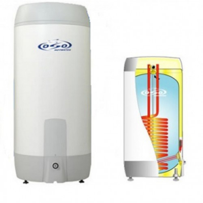
AT the simplest design buffer tank (heat accumulator, storage tank) is a heat-insulated metal tank with four branch pipes: two for the boiler circuit and two for the circuit heating system.
At the top of the device, there is a blast valve, which, if necessary, relieves excess pressure. At the bottom this device a drain valve is installed, thanks to which the coolant can be drained. In some models of the heat generator, the presence of an electric heating element and (or) a coil is provided for heating the coolant from other heat sources. Quite often, a heat exchanger is located in the upper part of the structure, thanks to which water is heated for hot water at home.
The principle of operation of this device is as follows: the tank is filled with coolant. When starting the boiler circulation pump the boiler circuit supplies cooled coolant from the bottom of the heat accumulator, which, after heating, enters upper part buffer capacity. Hot coolant is lighter than cold coolant, so it is always at the top of the tank. While the solid fuel boiler is operating in a small circle (only through the buffer tank), the cold coolant is gradually replaced by a hot one.
After the entire coolant has warmed up, the circulation pump of the heating circuit is turned on, the heated coolant from the top of the tank begins to flow into the heating system. The cooled return goes to lower part storage tank, and from there to the boiler. 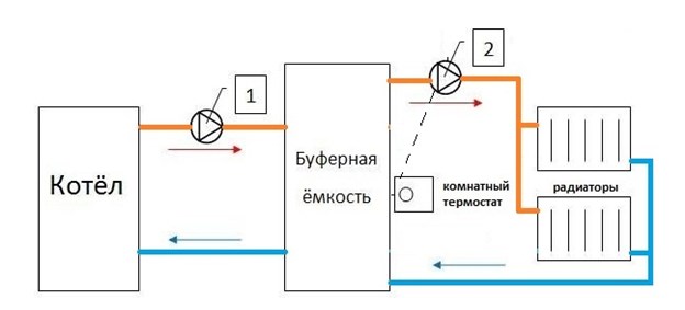
Due to the difference in density, the hot and cold coolant in the buffer tank practically does not mix.
The main advantages of such a heating scheme are that when the boiler stops this system for some time it will supply the radiators with hot coolant. Correct selection buffer tank for a solid fuel boiler can significantly increase the time between boiler fires, reduce fuel consumption and save money. In addition, the use of this device will smooth out temperature fluctuations in the boiler and heating circuit.
The disadvantage of heating with a heat accumulator is that between the start of the boiler and the heating of the radiators, enough big period. Depending on the room temperature and tank capacity, this time can be 2-4 hours.
Let's digress a little, because we want to inform you that we have compiled a rating of solid fuel boilers by mode. You can learn more from the following materials:
Strapping scheme
The heat generator cannot function correctly without piping.
The heat generator is installed parallel to the boiler unit and the heating circuit in the gap between them. The piping of a solid fuel boiler with a buffer tank includes two circulation pumps for the boiler and heating circuits, a three-way valve (for the boiler circuit) and a balancing valve (for the heating circuit), an expansion tank, a blast and drain valve, and a pressure gauge. 
- Three way thermostatic valve on the boiler circuit creates the movement of the coolant along the small circuit until its temperature reaches the set value. After heating the coolant, the valve blocks the movement of the hot coolant, and opens the way for the return flow from the heat accumulator. Installed between flow and return on the boiler circuit.
- The balancing valve will allow you to regulate the return temperature by adding a hot coolant to it in order to prevent the formation of condensate on the boiler heat exchanger. The balancing valve on the heating circuit protects the radiators from overheating by reducing the coolant supply (bypassing the heating system) to the return.
- Expansion tank compensates thermal expansion coolant.
- The blast and drain valve is a safety group that works in case of excessive coolant pressure. A pressure gauge is an element of a safety group that shows the pressure in the system.
- Filter coarse cleaning return line is installed to protect the three-way valve
- Do not forget about installing a cooling valve on the supply pipe, which, when the coolant temperature exceeds 90 ° C, mixes tap water into it.
The piping scheme of a solid fuel boiler with a buffer tank, as a rule, includes circulation pumps that move the coolant along the circuits.
Tip: For correct operation system, it is necessary that the output of the heating circuit pump is slightly higher than the output of the boiler pump. For a house up to 300m2, required parameters boiler pump 25/40; (25 mm connection diameter, 40 - head 4 m.); pump parameters for the heating circuit 25/60 (25 mm connection diameter, 40 - head 6 m.). Fine adjustment is made after the initial start-up of the system.
A rough calculation of the buffer capacity of a solid fuel boiler is made according to the algorithm: for 1 kW of boiler plant power, a tank is needed, with a volume of 20 to 40 liters. It is these indicators that allow the system to work most efficiently. You can calculate the volume of the tank more accurately (up to a liter), but then you will have to take into account: the heated area, calculate the heat loss of the home under various weather conditions, find out the amount of coolant that the system needs per hour of operation at the lowest temperature in your area. The time between the furnaces of the boiler plant must be multiplied by the calculated value. The result obtained will be the volume of the heat accumulator necessary for your system.
How to make a battery tank yourself
 Due to the fact that these installations are quite expensive, many of our compatriots ask: “How to make a buffer tank for a solid fuel boiler with your own hands?” In principle, nothing is impossible for a person with “straight hands”, knowledge of the basics of heat engineering, who has necessary material, a tool, the skills to use it and an obscene amount of free time.
If you have all of the above, then you must:
- weld a sealed container of the required volume; Need to use stainless steel, not less than 1.5 mm thick.
- make a tie-in of fittings with a diameter of 1 inch and with the necessary thread for connection with boiler equipment and heating system;
- embed a demolition valve in the upper part of the device, and a drainage valve in the bottom;
- insulate the tank with basalt fiber, 100 mm thick.
- weld a casing made of thin galvanized steel, based on the external dimensions of the heat-insulated tank.
- Install the device on the legs.
- Color the device.
Based on experience, it will not work to save money on making a heat accumulator for a solid fuel boiler with your own hands. For almost the same money, a new battery tank will be safer, more durable and more functional.
Solid fuel boilers are used to heat cottages and suburban households in the absence of the ability to connect to a gas main. They are excellent and efficient heat sources. And the main mistake of consumers is the choice of the simplest connection scheme. In fact, the operation of the system can be made more stable and correct. Let's see how a piping scheme for a solid fuel heating boiler is created and what components are found there.
Traditional solutions and their disadvantages
If a solid fuel boiler is the simplest heating device, this is not a reason not to pay attention to the presence of piping. Without it, it is almost impossible to make a well-functioning heating system that lacks users with its shortcomings. Let's see what threatens the absence of certain elements:
- No expansion tank - most serious mistake, as it should be mandatory. When heated, water tends to expand, trying to break the pipes. Therefore, expansion tanks are built into the heating. They can be traditional or membrane - for open and closed systems heating;
- There is no safety valve in a closed system - it is fraught with excess pressure in the circuit. Firewood does not burn as evenly as gas fuel, therefore, pressure and temperature surges in wood-burning heating systems are considered normal;
- There is no circulation pump - throwing thin polypropylene pipes onto the boiler, you will encounter their high hydrodynamic resistance. Therefore, a circulation pump should be included in the piping scheme of a solid fuel boiler, preferably with a bypass;
- No collectors - fraught with problems when using several parallel-connected circuits (uneven heating);
- There is no air vent - the absence of this element in the piping scheme threatens to air the system;
- No three-way valve - not the most necessary part, but it helps to prevent condensation;
- No buffer capacity - very interesting element in the piping scheme of a solid fuel boiler, which allows to stabilize the temperature in the circuit. Its absence threatens with temperature fluctuations and the need to throw fuel into the furnace too often.
So, a solid fuel boiler must be properly tied up so that the heating system is balanced, durable and safe.
The piping of a solid fuel boiler must necessarily include expansion tank.Not a single scheme can do without it. It can be purchased or homemade, but the fact is that it must be mandatory. In open heating systems, the simplest tanks are used, freely communicating with the atmosphere. In closed heating circuits, so-called membrane tanks are used, inside of which there is a rubber membrane.
The piping scheme for a solid fuel heating boiler with a membrane tank is not much different from the scheme with a traditional tank, except that some other elements are added to it, which will be discussed in the following sections of our review. The tank in closed heating systems is placed in an arbitrary place, for example, next to a solid fuel boiler or at any other point.
As for heating piping schemes open type, then here the tanks are installed at the highest point. This approach allows you to get rid of airing the circuit - air bubbles leave the system through the tanks. Safety valves are not needed here, since there is no excess pressure here.

Security group
Developing a piping scheme for a wood-burning boiler using closed system heating, it is necessary to install not only an expansion tank, but also a safety group. It includes three main elements:
- Manometer - indicates the current pressure in the circuit;
- Safety valve - relieves pressure;
- Automatic air vent - removes air from the heating system.
Let's see why certain elements are needed in the solid fuel boiler piping scheme.
Closed heating systems are sealed. The coolant in them does not come into contact with atmospheric air, as is the case in traditional open circuits. With excessive heating of the coolant, a situation may arise when, due to its expansion, the pressure in the circuit becomes too high. The pressure gauge in the piping scheme allows you to monitor the situation and take action. To do this, the entire safety group is installed next to the solid fuel boiler.
Instead of pressure gauges, thermomanometers can be used - they show not only the pressure in the system, but also the temperature in the circuit.
The safety valve in the piping circuit of a solid fuel boiler allows you to instantly relieve pressure when it is exceeded. The coolant and air are partially ejected through it. Its presence in closed-type heating is mandatory. As for the air vent, it removes the air masses accumulated in the system.
The piping scheme for a solid fuel boiler with a circulation pump is used in open and closed systems. It allows you to improve the circulation of the coolant. This is true for large households, including multi-storey ones. This approach is also practiced if thin plastic or metal-plastic pipes. Together with numerous bends and transitions, they create excessive hydrodynamic resistance that prevents the normal flow of the coolant.
For example, tying a solid fuel heating boiler with polypropylene without a circulation pump can lead to the following troubles:
- Overheating of the coolant due to the lack of normal circulation;
- Overheating of the boiler itself - this threatens to damage the heat exchanger;
- Cold spots in the heating circuit - some rooms will be cold.
Having put polypropylene pipes on the boiler and radiators, be sure to take care of installing a circulation pump.
Circulation pumps are also used in traditional gravity systems heating with solid fuel boilers. The use of such piping schemes eliminates the need to install pipes at a slight slope, as required by the scheme with natural circulation coolant. They also allow you to increase the size of the heating system, which is important for large households.
In the piping scheme of a solid fuel boiler, the circulation pump is placed on the supply or return pipe. The installation is carried out using a bypass - this approach allows you to start natural circulation at any time when the coolant is already warming up. Also, the presence of a bypass opens up the possibility of repairing or replacing the circulation pump without stopping and draining the water from the heating.
Application of buffer tank
The piping scheme for a solid fuel boiler with a battery tank is not widespread. It is quite bulky, but allows for more correct operation of heating. Its advantages:
- Stabilization of the temperature in the system due to the increased volume of water in the circuit;
- The possibility of reducing the number of approaches for laying fuel in the boiler furnace due to the accumulation of excess heat in the storage tank;
- The possibility of accumulating obviously unnecessary excess heat energy when using a too powerful boiler or excessive firewood.
The scheme with a heat accumulator has one drawback - it is necessary to allocate space for the device itself. The volume of the used container reaches several hundred liters, so you will need free space to accommodate the tank.
There are many schemes for connecting buffer tanks. The simplest of them involve the use of the same coolant in the boiler and in the heating system. More efficient scheme- using a three-way valve with a thermostat, which ensures a more uniform and economical consumption thermal energy from the buffer tank.
Also, schemes with two circuits are used. In this case, heat accumulators of heating systems are equipped with heat exchangers connected to solid fuel boilers. Heat exchangers heat the water in the tank, which is the heat carrier of the heating circuit. This option is distinguished by its efficiency and more uniform heating.
This scheme with a buffer tank is gentle for solid fuel boilers that are not designed for high pressure in heating. And in this case, the heat carriers will be separated, the pressure in the tank and in the radiators will not affect the pressure in the boiler itself and the heat exchanger.
The use of a single-circuit solid fuel boiler often forces one to look for schemes for organizing hot water supply. For these purposes, you can adapt the cumulative or instantaneous water heater. It is also possible to use a more advanced heat storage tank with a built-in coil DHW circuit. Such a strapping scheme will become optimal and profitable solution, as it will solve the problem with hot water supply.
Application of additional boilers
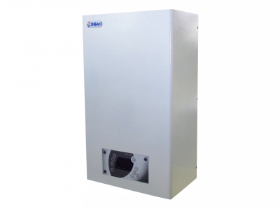
In the piping scheme of a solid fuel boiler, you can include quite unusual element is an electric boiler. It cannot be called a harness, it is rather a simple duplicating addition. Such schemes are activated in the absence of space for the placement of a heat accumulator. The electric boiler works in tandem with a wood-burning unit, automatically turning on when a temperature drop in the circuit is detected. Benefits of the scheme:
- Maintaining a stable temperature in heating;
- No need to spend money on a tank - the simplest electric boiler costs only a few thousand rubles;
- The possibility of heating in the temporary absence of firewood;
- A good night's sleep, because you don't have to jump out of a warm bed to throw the next portion of firewood into an insatiable firebox.
There are also disadvantages:
Among other things, the use of a backup electric boiler is extremely inefficient if there are accidents in your area. frequent interruptions with electricity.
- A backup electric boiler consumes a lot of electricity, which leads to an increase in the cost of operating the heating system - this is not the most profitable scheme;
- To power a powerful boiler, you will need separate line and good electrical wiring;
- especially powerful models electric boilers require connection to a three-phase network.
Therefore, the investment in the purchase of a heat accumulator will be more profitable.
Using a three-way valve
When creating a piping scheme for a solid fuel boiler with your own hands, you should consider the need to install a three-way valve. A properly designed heating system should not show the biggest difference between the temperature of the water in the return and supply pipes - usually it ranges from 20-30 degrees. But sometimes this parameter goes beyond the norm, due to which the temperature in the "return" drops.
It would seem that there is nothing to worry about, since a solid fuel boiler will in any case bring the coolant to a predetermined temperature. But in practice, this often leads to the formation of condensate, which causes corrosion. A three-way valve helps to neutralize this phenomenon. It is installed between the supply and return pipes, mixing a hotter coolant from the supply to the "return".
As a result of mixing, the temperature in the heating return pipe rises, due to which the formation of condensate becomes impossible. Together with the three-way valve, a temperature sensor is supplied that measures the return temperature. As soon as its temperature reaches the norm, the mixing of the hot coolant will stop.
Please note that in this solid fuel boiler piping scheme, the circulation pump must be located between the valve and heating unit and not somewhere else.
Indirect water heaters
An indirect water heater will provide a stable and efficient work the entire heating system.
Piping scheme for a solid fuel heating boiler using a boiler indirect heating not the easiest, but not the most difficult either. Here, consumers are faced with the task of ensuring the supply of hot coolant from the heating circuit to the coil. To do this, a hydraulic arrow is placed in the system, distributing flows in two or more directions. Two pipes depart from the arrow - one goes to the batteries, and the second to the boiler.
Two circulation pumps are placed behind the hydraulic arrow - the complexity of the piping scheme is gradually increasing. One pump sends the coolant to the radiators, and the second drives it to the boiler. The operation of the second pump is controlled by a thermoregulation system built into the water heater. This ensures that a stable temperature is maintained in the DHW circuit.
Water guns and collectors
The use of hydraulic arrows and collectors in the piping schemes of solid fuel boilers makes it possible to ensure the supply of coolant in several directions - to radiators, underfloor heating, heated towel rails and boilers. Collectors distribute the coolant evenly, at each outlet it has the same temperature. Further, the coolant is picked up by circulation pumps and carried away in the required direction.
Hydro arrows allow you to distribute the coolant by temperature. If there are two collectors in the heating system (one is placed on the supply pipe, and the second on the return pipe), then the hydraulic arrow is installed alone and connected to two pipes at once. Inserts are made in it, allowing you to take the coolant different temperatures- for example, in warm floors not needed too heat, so it can be taken closer to the return pipe.
Pyrolysis boiler piping
The piping scheme for a pyrolysis solid fuel boiler is not much different from the piping scheme for a boiler with direct combustion of firewood. Here it is necessary to focus on the type of heating system (open or closed, with natural or forced circulation), for the presence of additional circuits (warm floors), as well as for the presence of connected water heaters. In accordance with this, we develop a strapping scheme based on the elements described above.
Video
The piping of a solid fuel heating boiler should take into account all the features of this type of thermal energy generators, as well as the complexity and composition of the heating system itself: the number of circuits, the circulation scheme, the method of wiring and regulating the supply of coolant. In addition, the piping scheme for a solid fuel heating boiler should be chosen so as to ensure not only the greatest efficiency, but also the maximum safety of its operation. In this article, we will consider several schemes of varying complexity that can be used, depending on the type and complexity of the heating system.
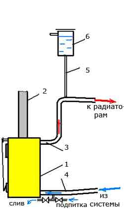
Fig.1 Diagram of boiler piping in an open system with natural circulation
The simplest is the piping scheme for a solid fuel boiler for single-circuit system heating with natural (gravitational) circulation of the coolant. As a rule, metal (most often steel) pipes are used in such systems with respect to large diameter corresponding to the diameter of the outlet and inlet pipes of the boiler. It is best if their diameter is the same. This will allow, along with other factors, to reduce hydraulic resistance and create Better conditions for natural circulation. Such schemes are characterized by maximum simplicity, and when piping the boiler, it is necessary to try to avoid unnecessary elements that, to one degree or another, impede the natural movement of the coolant. Therefore, it is necessary to use shut-off or control valves to a minimum and only in places where it is impossible to do without them. Also, the presence of various filters in the circuit of such a system is undesirable. Most of these systems are open. The expansion tank in them performs the function of creating excess pressure and venting air, therefore it is installed at the highest point, at the highest possible height (under the ceiling or in the attic).
On fig. one: 1 - boiler; 2 - chimney; 3 - supply pipe (diameter 40-50 mm); 4 - "return" (diameter 40-50 mm); 5 - pipe (1/2); 6 - expansion tank of open type.
In systems with combined circulation
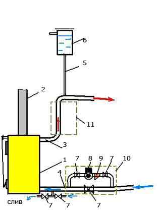
Fig.2 Strapping scheme for open system with combined circulation
The scheme for a system with combined (combined) circulation is more complex, since it already provides for the presence of a special circulation pump in it, as well as necessary elements its piping (bypass, stop valves, filter mechanical cleaning, air valve). A bypass with a circulation pump can be installed both on the supply pipe and on the “return”, depending on the availability of space for installation and the convenience of further maintenance.
The air valve is included in the bypass if it is installed on a horizontal section of the pipe and the design of the pump itself does not provide for the possibility of bleeding air.
In the event of a power failure, the tap on the direct bypass pipe opens and the system operates with natural circulation. Instead of a tap, a valve is sometimes installed in this place, which opens automatically in the absence of electricity.
On fig. 2: 1 - boiler; 2 - chimney; 3 - supply pipe; 4 - "return"; 5 - pipe 1/2 "; 6 - expansion tank; 7 - shut-off valves; 8 - circulation pump; 9 - filter; 10, 11 - possible locations of the bypass on the "return" or supply line.
If the heating system is closed, then instead of the usual open expansion tank a sealed membrane is installed. This allows you to provide the specified overpressure(usually it is about 1.5 bar (0.15 MPa). In addition, such a scheme must necessarily include a safety block ( safety valve, manometer, air valve).
Recently, piping of a solid fuel boiler with polypropylene has been increasingly used, that is polypropylene pipes and fittings. This material has become quite popular, as it is not subject to corrosion, easy to install and has a relatively low cost.
In this case, it is necessary to remember such features of solid fuel heat generators as a large inertia and the difficulty of quickly controlling the combustion temperature of the fuel, and hence the coolant. Therefore, when tying such a boiler with polypropylene, it must be remembered that the supply pipe coming out of it must be metal at a distance of at least 1.5 m or until the first branch. The "return" can be completely plastic, since the temperature of the liquid in it rarely exceeds 70-80 ° C. But its inner diameter must correspond to the inner diameter of the metal supply pipe.
Piping schemes in systems with a hydraulic separator
In more complex systems that include several circuits (branches), solid fuel boilers with a hydraulic separator are often used in the form of a cylindrical tank, the top of which is supplied with a heated coolant, and the bottom with cooled liquid from the system. From the upper part of the hydraulic separator, water is supplied to the comb (collector) and distributed between the circuits, and from the lower part to the boiler inlet pipe. Such schemes are usually used for closed systems with forced or combined circulation. Below are two possible options.
Option 1
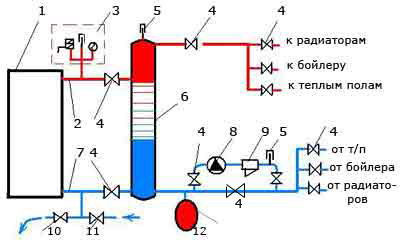
Fig.3 Boiler piping scheme with hydraulic separator (option 1)
In Fig.3: 1 - boiler; 2 - supply pipe; 3 - safety block; 4 - crane; 5 - air valve; 6 - hydraulic separator; 7 - return pipe; 8 - circulation pump; 9 - filter; 10.11 - taps for draining and supplying water; 12 - membrane tank.
Option 2
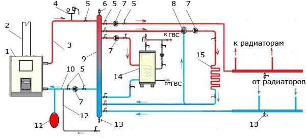
Fig.4 Piping scheme with hydraulic separator (option 2)
In Fig.4: 1 - boiler; 2 - chimney; 3 - heated water; 4 - safety block; 5 - crane; 6 - air valve; 7 - circulation pump; 8 - three-way thermal valve; 9 - hydraulic separator; 10 - "return"; 11 - membrane tank; 12 - feed cold water into the system; 13 - drain valve; 14 - boiler; 15 - warm floor.
Scheme with a heat accumulator
Sometimes the so-called buffer tank or heat accumulator is included in the water heating system. This allows you to accumulate thermal energy during operation of the solid fuel boiler and use it to heat the room in the intervals between the furnace. The piping scheme for a solid fuel boiler with a heat accumulator usually includes shut-off and control valves, pump groups with a control unit, which ensure that one or another circuit is turned on or off and the entire system works efficiently.
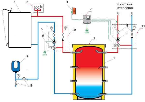
Fig. 5 Boiler piping scheme in a system with a heat accumulator
In Fig.5: 1 - boiler; 2 - safety block; 3 - electrical shield; 4 - buffer tank (heat accumulator); 5 - circulation pump; 6 - three-way thermal valve; 7 - control unit; 8 - cranes; 9 - membrane tank; 10,11 - pumping groups.